 |
| Wind Farm operation |
| · Monthly production charts |
| General Info |
| · CRES Wind Farm |
| · Technical specs of the WTs |
| · Monitoring & control of the wind farm |
· Installation photos |
| · Hydrogen Production |
| · Related articles |
3.01 MW Demonstration Wind Farm
Various
Wind Energy technologies in Complex Terrain topography
Location:
Lavreotiki, SE Attica, Greece
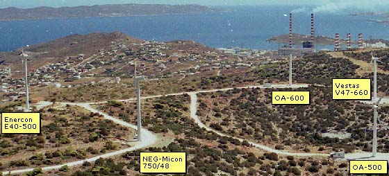
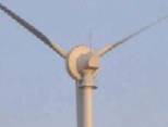
( Photo taken from the 100m high meteo-mast,
situated NNW of the Wind Farm, before the nacelle installation of the
��-600 )
On-Line monitoring of the Wind Farm, using a mobile phone:
Send an SMS message with the character ? to +30 6944 560 987 and you will receive instantly the last 10min statitistics of the Wind Farm operation.
|
|
|
|
|
|
|
|
|
ENERCON |
|
|
������ �.�. |
������ �.�. |
| |
E40-500 |
V47-660 kW |
NM 750/48 |
OA500 |
OA600 |
������ Rotor |
|
|
|
|
|
| Diameter: |
40 m |
47 m |
48.2 m |
39.83 m |
40.58 m |
|
Area swept: |
1275 m2 |
1735 m2 |
1824 m2 |
1246 m2 |
1293 m2 |
| Speed of revolution: |
variable, 18 - 38 rpm |
28.5 rpm |
22/14 rpm |
Variable,
OPSC � (Opti Power Speed Control) � |
Variable,
OPSC � (Opti Power Speed Control) � , |
|
Number of blades: |
3 |
3 |
3 |
3 |
3 |
| Length of blades: |
19 m |
|
|
|
19m |
|
Blade material: |
fiberglass (reinforced epoxy) with integral lightning protection |
|
|
LM 19.1 Type (Denmark) stall type,
with integral lightning protection |
LM 19.1 Type (Denmark) stall type,
with integral lightning protection |
| Tip speed: |
38 - 80 m/s |
|
|
|
|
| Type: |
upwind rotor with active pitch control |
Upwind rotor |
Upwind Rotor |
Upwind rotor |
Upwind rotor |
| |
|
|
|
|
|
������ Tower |
|
|
|
|
|
| Type: |
|
|
Conical, steel, painted |
Steel, painted Quality St52-3N |
Steel, painted Quality St52-3N |
| Hub height(approx,) |
44m |
45m |
45m |
38 m |
38 m |
| |
|
|
|
|
|
��� Generator |
|
|
|
|
|
| Type: |
direct-driven
ENERCON ring generator (with drive train) |
Asynchronous with OptiSlip� |
Asynchronous, 4/6 pole |
3 phase, Asynchronous, 4 pole |
3 phase, Asynchronous, 4 pole |
|
Name plate rating: |
500 kW |
660 kW |
750/200 kW |
573 kW (ambient temp. 40�C, 29rpm), 530kW continuous (ambient temp. 47�C, 29rpm, or 40�C, 25rpm) |
670 kW (ambient temp. 40�C, 29rpm), 600kW continuous (ambient temp. 48�C, 29rpm, or 40�C, 24rpm) |
| Nominal Voltage: |
|
690 V |
690 V |
690 V |
690 V |
|
Nominal frequence: |
50 Hz |
50 Hz |
50 Hz |
50 Hz |
50 Hz |
| Hub: |
Rigid |
|
|
|
|
| Cooling: |
|
|
Liquid-cooled with pump |
Self cooled |
Self cooled |
| |
|
|
|
|
|
Operational
data |
|
|
|
|
|
| Nominal output: |
500 kW |
660 kW |
750 kW |
500 kW |
600 kW |
|
Cut-in wind speed: |
2.5 m/s |
4 m/s |
4 m/s |
4 m/s |
4 m/s |
| Cut-out wind speed: |
|
25 m/s |
25 m/s |
None |
None |
|
Nominal wind speed: |
12 m/s |
15 m/s |
16 m/s |
14.5 m/s |
14.5 m/s |
| Power regulation: |
|
Pitch/OptiSlip� |
Stall |
Stall
+ OPSC � + ALPC� |
Stall
+ OPSC � + ALPC� |
| |
|
|
|
|
|
��� Gearbox |
|
|
|
|
|
| Type: |
|
Planet/parallel axles |
Planetary - parallel axle |
Full third base Planetary heavy type |
Full third base Planetary heavy type |
|
Ratio: |
|
|
1:68.2 |
1:52.18 |
1:52.18 |
| Main shaft: |
|
|
Forged shaft and flange |
|
|
|
Main bearing: |
double-row tapered roller bearings |
|
Spherical roller bearing |
2 elastically couplings, one on the low-speed shaft
and another on the high-speed shaft to the generator |
2 elastically couplings, one on the low-speed shaft
and another on the high-speed shaft to the generator |
| Cooling: |
|
|
Liquid-cooled with pump |
2 independent oil flow/cooling circuits |
2 independent oil flow/cooling circuits |
| |
|
|
|
|
|
���� Control |
|
|
|
|
|
| Braking system: |
3 independent pitch-control systems with emergency supply rotor brake rotor lock for service and maintenance |
Air brake: Feathered. |
Blade tip air brake: Hydraulic, fail-safe Disk brake: Hydraulic, fail-safe |
� 2 Disk brakes. 2 independent hydraulic circuits (low-speed & high-speed brake, fail-safe emergency type) �
Normal
braking to zero speed via inverter current (public network
intact, no emergency!) �
Emergency
braking via DC current powered from inverter (Emergency but
network intact) �
Over-torque
limiting system (in case of generator short-circuit). |
� 2 Disk brakes. 2 independent hydraulic circuits (low-speed & high-speed brake, fail-safe emergency type) �
Normal
braking to zero speed via inverter current (public network
intact, no emergency!) �
Emergency
braking via DC current powered from inverter (Emergency but
network intact) � Over-torque limiting system (in case of generator short-circuit). |
|
Yaw control: |
active through adjustment gears, friction damping |
|
Type: Ball bearing Yaw Brake: 3 Friction brake/motor brake Drive mechanism: 4 electrical planetary gears |
�
Ball bearing �
2 friction fail-safe
type electrical motor brakes � Speed and continuous soft position control. |
�
Ball bearing � 2
friction fail-safe type electrical motor brakes � Speed and continuous soft position control. |
| Type: |
|
Microprocessor - based control
of all turbine functions with the option of remote monitoring. |
Type: Computer controlling Computer controlling: Soft by thyristors Capacitor bank: No-load compensated Remote control: By modem |
|
|
| |
|
|
|
|
|
���� Sensors |
|
|
|
|
|
| RPM sensors: |
|
|
Rotor, generator, yaw system |
Pulse generator on generator shaft |
Pulse generator on generator shaft |
|
Temperature sensors: |
|
|
Gear, generator, controller |
Gear, generator, controller,hydraulic,
ambient,bearings, drive |
Gear, generator, controller,hydraulic,
ambient,bearings, drive |
| Thermal sensors/warning: |
|
|
Main switch, engine protection |
|
Gear, generator, controller,hydraulic, ambient,bearings,
drive |
|
Vibration sensor: |
|
|
Nacelle, rotor |
|
|
| Meteorology: |
|
|
Anemometer, wind vanes, thermometer |
|
|
| Hydraulic systems: |
|
|
Pressure sensitive switches, pressure transducer |
Pressure sensitive switches, pressure transducer
|
Pressure sensitive switches, pressure transducer
|
| |
|
|
|
|
|
Lightning
protection |
|
|
|
|
|
| Type: |
|
|
According to standard IEC 1024 |
Lightning protection of all mechanical � electrical � electronic systems, from blade tips to base of tower. |
Lightning protection of all mechanical � electrical � electronic systems, from blade tips to base of tower. |
|
Blades: |
|
|
Receptor in the blade tips |
|
|
| Nacelle: |
|
|
|
|